The new template approach to creating interactive 3D PDFs does not require programming or scripting.
3D manufacturing models are seen by many eyes, not just the people who use CAD to create and review them. Lattice Technology has long been one of the leading companies in the narrow niche of making tools to view complicated 3D models, such as the complete design of a wide-body passenger jet.
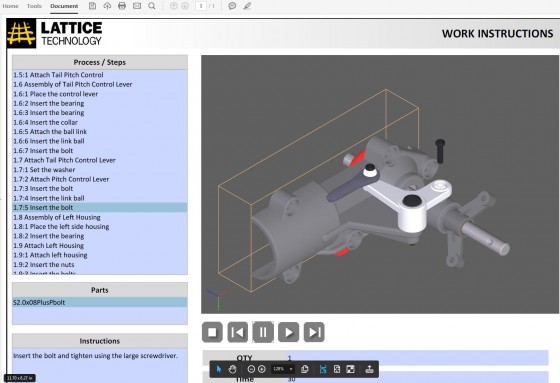
The newest edition of Lattice3D Studio makes it easier to create interactive 3D PDFs readable on any current copy of Adobe Reader. The end product is an interactive document with animations and linkages to process steps and parts lists. It is not necessary for either the PDF creator or the readership to have access to a specific CAD product.
New features in version 13.2 include:
Visualization of the BOM: As parts are selected to be included in the manufacturing Bill of Materials (BOM), they disappear from the 3D rendering. Manufacturing engineers know there are major differences between the engineering and manufacturing BOMs. Lattice says one of Studio’s primary benefits to the manufacturing company is easy authoring of manufacturing BOM directly from the engineering BOM.
Collision detection for assembly planning: The complete assembly process can now be planned within Lattice3D Studio. The software will recommend part movements along their axis, which can be overridden by the user. It will then capture any clash that occurs from the defined part movement. The affected parts will then be highlighted and “key frames” created. With Lattice3D, a keyframe is an interactive, 3D animation. Because the keyframe is interactive 3D, the user can rotate and reposition it to see any angle in order to thoroughly understand the collision. This interactive animation can then be used to modify the assembly process or to send it back to engineering for modification.
Advanced renderings directly from CAD models: New features make it easier to generate high-quality renderings. Up to 6 cutting planes can now be specified, providing illustrators more options for depicting inner assembly workings. In addition, the “single spot” light source has been added, for additional rendering realism.