Fibersim update streamlines composite product development

The update continues the software’s automation of aligning composite engineering with other product data in CAD and PLM.

Siemens PLM has updated its Fibersim portfolio of software for composites engineering, used primarily in aerospace, automotive, marine, and wind energy.

A meshed surface from an analysis model (upper right) highlights ply coverage. The jagged ply boundary (green curve) is smoothed (blue curve) using Fibersim 13. The software allows information from the analysis model to be reviewed, modified and imported, streamlining product development communications. (Source: Siemens PLM)

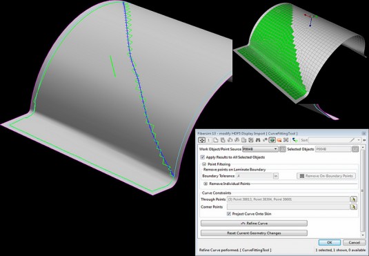
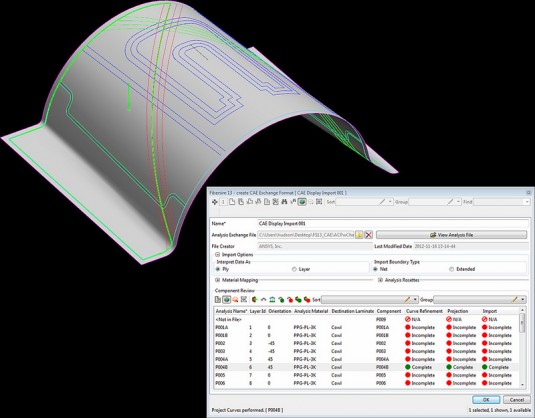
Fibersim 13 adds new functionality for bi-directional exchange of simulation and analysis data with CAD, to help users avoid tedious, error prone data re-entry. The new capability directly integrates analysis data into the design environment, enabling automatic design updates based on analysis results. The software also provides new design-for-manufacturing processes that support optimization for parts designed to match the manufacturing definition and then trimmed to the engineering definition.

Fibersim 13 also extends its integration with Siemens’ Teamcenter PLM software to associate manufacturing datasets—such as flat patterns, laser data and automated deposition data—to the proper model revision and subsequently communicate this information to the factory floor. Siemens says this integration delivers consistent datasets to manufacturing and to facilitate fabrication of products according to the latest design.

The update is now available to Fibersim users.

Fibersim 13 provides a single location for the automatic association of engineering information with a CAD model. As changes are made, the designer can identify, modify and apply changes. Users can also identify completed work during the review of analysis data. This image shows that curve refinement was completed and changes to the ply information have been applied. (Source: Siemens PLM)