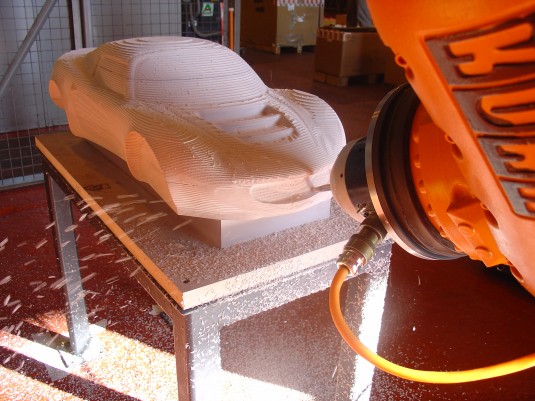
Robot milling is preferred for large parts and custom sculpting. The completely rewritten interface is now part of PowerMill.
Delcam has launched a new robotic interface for the programming of robots for multi-axis machining operations. Their previous Visual Basic application developed for robot machining has been completely rewritten and fully embedded inside the company’s PowerMill CAM system as a plug-in.
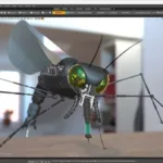
Delcam claims the new interface “makes it as easy to program a robot for machining as it is to program a five-axis machine tool.” users have access to all the multi-axis machining strategies within PowerMill and can use all the system’s project management options to manage, store and retrieve data.
Three-step process
The core functionality of the PowerMill Robot Interface consists of three main steps: programming, simulation (including analysis) and creation of the robot programs. Robots can be programmed for tool-to-part applications, making them useful for machining large parts, such as composite panels that need to be trimmed, or for part-to-tool applications, such as grinding or finishing. The working area can be extended with linear tracks and rotary tables for even greater flexibility over the size and types of parts that can be manufactured.
The PowerMill Robot Interface can then be used to simulate the complete machining operation and to control the robot’s movements through different variables, such as axis limits, axis priorities and workplane constraints. Various aspects within the configuration of the robot cell, such as axis limits, tool constraints and home position, can be defined, and the simulation of the robot completed within those constraints.
The robot’s working envelope can be displayed to optimize the position of the part or initial stock, and so give maximum access to the material. The maximum range of movements required of each axis can be viewed to analyse the robot’s behavior and movements throughout the operation.
Any issues that may prevent the toolpaths from being completed successfully are highlighted, with notifications of the robot potentially reaching axis limits, singularities and collisions. Graphs display the axis limits, wrist singularity and axis reversals, to give a better understanding of how the robot will move. Similarly, the acceleration and deceleration of the robot’s axes are shown on time-based graphs.
Once the results of the simulation have been reviewed, and modified if necessary, the program can be output in the appropriate robot native language, for example for KUKA, ABB, Fanuc, Yaskawa Motoman or Stäubli equipment, eliminating the need for third-party translation software. Acceleration, smoothing values and other robot-specific parameters can be defined as part of the output. Full support for external axes, such as rotary tables and linear tracks, can be included, as well as dedicated tools for spindle calibration.
A video showing the PowerMill Robot Interface in action is posted at www.delcam.tv/cnc-polystyrene.